Fluid Simulation
Matthew Jee, mcjee@ucsc.edu
Project Overview
This goal of this project was to create a 3-Dimensional fluid simulator that would run at interactive framerates. My original goals were to implement a CPU Solver, a GPU Solver, and Volumetric lighting. I achieved the first 2 goals, but was not able to implement an effective volumetric lighting system. This fluid simulator has a volume renderer that does not perform any lighting calculations.
User Guide
Controls
- Left click and drag to move rotate the fluid domain.
- Right click and drag to add fluid.
- Press any key to enter/exit fullscreen.
Sidebar Options
- Velocity Scale: The speed of inserted fluid.
- Density Scale: The amount of inserted fluid.
- Iterations: Simulation Accuracy (the number of iterations the projection step should use).
- Subdivisions: The number of cells in the fluid domain.
- Erase Fluid: Clear the density and velocity fields.
- Samples: The number of teps the ray marcher should take.
- Colors: The color function of inserted fluid.
- Glow: Toggles additive blending.
- Dark Background: Toggles background black/white.
- Particles: Toggles particle simulation.
- Bounding Box: Toggles fluid domain bounding box visibility.
Solver
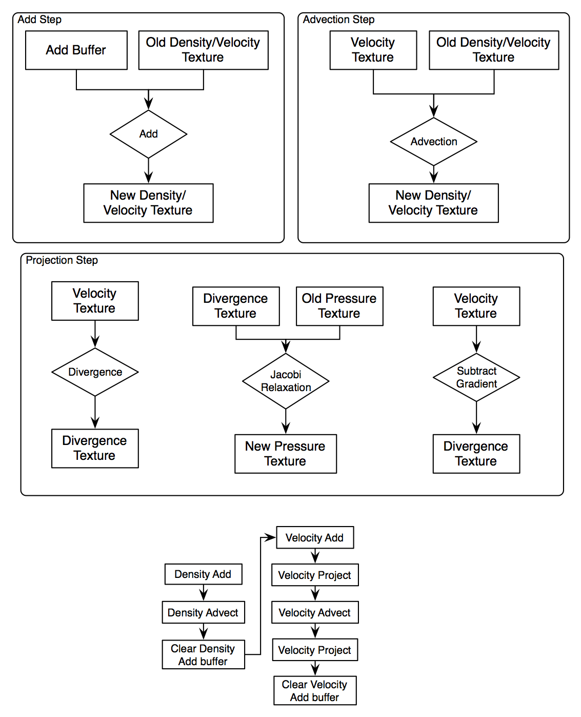
High Level Overview

Challenges
Note: All of the framerate listed below are based on testing on a Nvidia 330M, which is not very fast at all.
Speed was a major issue throughout the development process. The CPU Solver struggled to maintain 30 fps at very low (32 x 32 x 32) grid sizes, and just 1 color channel, even with a low (less than 10) iteration count. This is why the CPU solver is not accessible in the final product (the code is still there).
The GPU Solver is much more performant. It is able to compute at about 30 fps a 64 x 64 x 64 grid with 16 iterations and 4 color channels. That's more than 30 times as fast. The GPU Solver required several revisions to get it up to this speed.
In order to use OpenGL to run fluid simulation kernels, the GPU Solver renders a full screen quad, with a 2D texture corresponding to the volume data mapped to the quad. The fragment shader then takes samples of this 2D texture to do the simulation computation. To run computations on a volume, either each slice of the volume must be rendered separately, or the data representing the 3D texture must be mapped to a 2D texture. This project uses the latter approach.
Even with GPU Solving there were still speed issues. Initially I was using textures full 32-bit floating point components for the fluid volume, but this became too bandwidth intensive. The GPU Gems article suggested using half-precision floating point textures for speed up, so I implemented those and the framerate easily increased by about 1.5x. There is minimal loss of simulation quality when using low precision floats. Mike Acton's half-precision c implementation was used.
Derivation
Well, I did say I would derive the math. However, I have decided not to include the derivation because it is not very graphics related, and it would require a ridiculous amount of work to write it out on this page.
Renderer
High Level Overview

Challenges
I attempted to implement volumetric lighting, but the quality was to low for the speed penalty it induced. My method involved taking samples from each sample point to each light source, to determine occlusion by other parts of the volume.
The GPU Gems paper proposed a deferred rendering method. First the depth of back faces of the fluid domain would be rendered, then the positions of the front faces would be rendered and the depth of the front faces subtracted from the first pass. This deferred buffer would contain all the data necessary to perform ray marching over the fluid volume. I experimented with this, but it only slowed down rendering. It was faster to just use a conditional to terminate sampling rather than get depth values from a deferred buffer. It should be noted that compositing fluid with other geometry in a scene necessitates the deferred approach. Since I don't render any other geometry besides the fluid, deferred rendering was not necessary.
The blending used in the simulation is not physically accurate. For the non-additive blend shader, the volume samples are blended from front to back. This way, we can stop taking samples as soon as the front-most voxels obscure the back ones. This is faster than correct blending back to front.
Partway through the project I realized that using the density color channels as red, green, and blue parts of a single substance does not produce color the way I thought it would. The colors always turned out very dark and washed out. Instead, it turns out that having each color channel represent a unique substance with an arbitrary color works best. For the non-additive shader, red is the amount of red fluid, green is the amount of green fluid, blue is the amount of blue fluid, and alpha is the amount of white fluid. Using alpha as a white fluid allows for brighter colors.
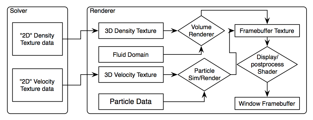
The solver density data is passed to the renderer though a pixel buffer object. By using a pixel buffer object, the data transfer is asynchronous, letting the CPU do other stuff while the pixels/voxels are transferred. This fluid simulator uses that extra time to run a particle simulation using the solver velocity data. Since this occurs alongside the density pixel transfer, the cost is minimal (though the velocity texture must be transferred first).